
M100
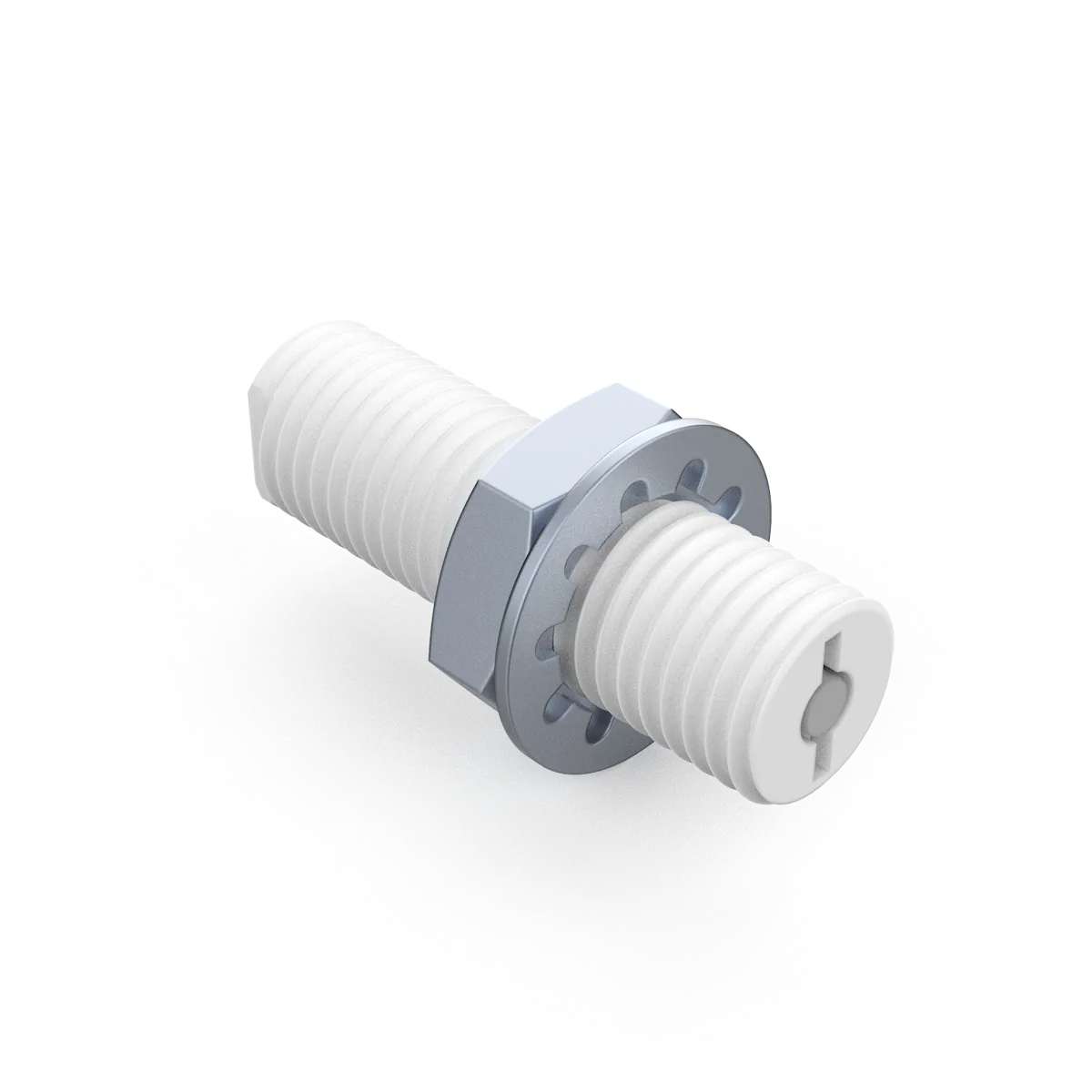 M100 / WEAR LIMIT MONITORING
WEAR-LIMIT MONITORING
A signal at the wear limit.
A prompt for maintenance.
Signals when wear reaches the preset position, prompting inspection and replacement of the linear slider liner.
Confirm the setpoint, tolerance and operating conditions. Replace the sensor after activation. This is not a continuous thickness measurement device.
Discuss mounting and compatibility ↗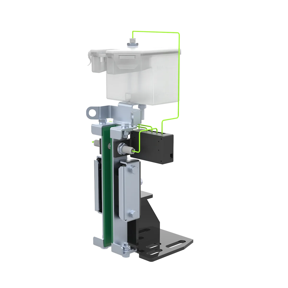
Monitoring system installation illustration. Verify the actual mounting position and clearance.
Choose a sensor or a monitoring system.
The sensor alone requires a controller and alarm. The optional monitoring system supports local visual and audible alarms and a Y0 output; interface logic requires integration testing.
| Sensor only | Specification |
|---|---|
| Supply | DC 2.5–24 V |
| Output | NMOS open-drain, active low; external pull-up required |
| Dimensions & mounting | M12 × 40 mm M12 thread; 40 mm length |
| Alarm setting | Liner wear depth: 0.5–3 mm; custom settings available |
| After activation | One-shot activation; replace sensor and verify the alarm |
Optional control board: DC 24 V ±10%, three wear inputs and an optional oil-cup level input. Control board functions do not apply to the sensor alone.
ENGINEERING ENQUIRY
Prepare your enquiry.
Create an email or copy the details to WeChat. This form does not submit or store your entries.
Email opens your mail app; send it there to complete your enquiry. zhuwentao@jjcnewmat.cn
DOWNLOADS / V18 · 2026-10-22
Download only what you need.
Bilingual PDFs · Select a chapter for a smaller download.